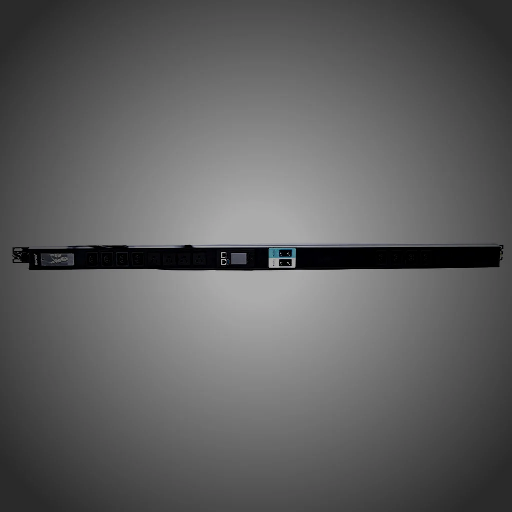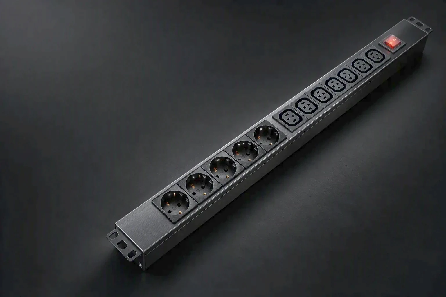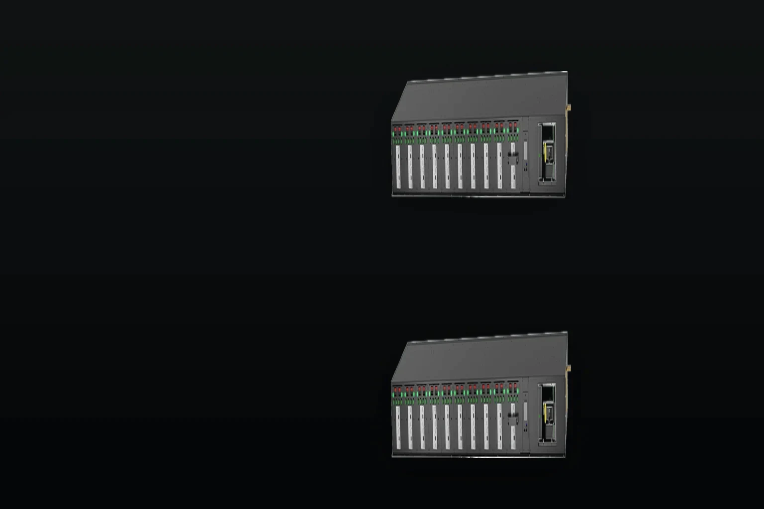
Two feeds in, one feed out
A dual-feed unit that carries both supplies into the rack and hands the load to the healthy one. Wide-range input from 180V to 265V with surge protection, on a 10A to 32A band.
- Feeds
- 2 in / 1 out
- Wide input
- 180–265V
- Current band
- 10A–32A
- Surge
- Fitted
- Reporting
- SNMP / Modbus
 Dual-feed parameters
What is fixed and what is drawn
The current band, the input window, the protection and the reporting path are published figures. The transfer mechanism and the outlet list are drawn per order, because they follow the rack the unit goes into.
- Feed arrangement
- 2 in / 1 out
- Wide-range input
- 180–265V
- Operating voltage
- 110V~250V AC
- Operating frequency
- 50Hz~60Hz
- Input current
- 10A–32A
- Output current
- 10A–16A
- Surge protection
- Fitted on the input
- Lightning protection
- Fitted on the input
- Overcurrent device
- Breaker or hydraulic-magnetic
- Ethernet
- 10/100M × 1
- Serial
- RS485 × 1
- Protocols
- SNMP · Modbus
- Web server
- Embedded
- Local display
- Industrial OLED, IP on screen
- Event storage
- Up to 20,000 entries, RTC held through power loss
- Outlet types
- IEC C13 10A · IEC C19 16A
- Outlet example
- C13 × 36 + C19 × 4
- Manual bypass
- Drawn per order, to the site procedure
 Built, not catalogued
Drawn to the rack it feeds
A transfer unit is built to the two supplies arriving at the cabinet, the outlet list the rack needs and the way the site expects to isolate a feed for maintenance.
- Feed arrangement2 in / 1 out
- Outlet listPer order
- Manual bypassPer order
- Outline drawingPer unit
 Protection
Both feeds protected
- Wide-range input180–265V
- SurgeFitted
- LightningFitted
- OvercurrentBreaker or hydraulic
 From requirement to mechanism
A single feed makes the rack a single point of failure
One cord, one breaker and one upstream panel sit between the rack and its workload. A second feed removes the upstream path, but only if the rack can use it: a transfer unit carries both supplies to the cabinet, protects each one, and presents the load side as a single feed the rack is already built for.
- Feeds carried
- Two, independently protected
- Load side presented
- One feed
- Wide-range input
- 180–265V
- Surge and lightning
- Fitted on the input
- Isolation for service
- Manual bypass, drawn per order
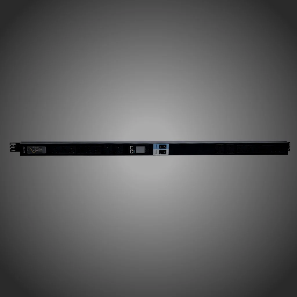
 What the unit reports
State of both feeds, on one reporting line
A transfer unit that cannot be read from the network is a black box between two supplies. These are the values the unit publishes, and where each one can be seen.
 Feed current
0.1A
Scale of the total current reading, at ±1% plus one digit, on the loaded feed.
Feed voltage
1V
Metering input range 90V to 350V, so a sag on either feed stays inside the window.
Energy
0.1kWh
Energy total at 1 grade, which is the figure a billing line is written against.
 Protocols
2ways
SNMP and Modbus over 10/100M Ethernet or RS485, with an embedded web server.
 Event storage
20,000
Entries kept on the unit with an RTC that holds through power loss.
 Units tested
100%
Continuity, polarity, insulation and function tested on every unit before dispatch.
 How an ATS is ordered
From the two supplies to the commissioning record
Three stages, in order. The two supplies and the isolation procedure are settled first, because the transfer mechanism and the bypass arrangement are drawn from them.
Supplies and isolation
Both incoming supplies, the current per feed and the way the site isolates a feed for maintenance are written down before anything is drawn.
Outline drawing
The transfer mechanism, both input protections, the bypass arrangement and the load-side outlet list are drawn by unit, and the revision is confirmed in writing.
Test and record
The unit is powered and tested: continuity and polarity per line, insulation per unit, the transfer checked on both feeds, and the metering readings recorded.
Dual-feed request
Describe both supplies, get the transfer drawing
State the current per feed, the outlet combination and how your site isolates a feed for service. The reply is a configured quotation with a specification sheet per line and an outline drawing for the cabinet.
Reply within 12 hours on working days · no lead time or minimum quantity figure is published on this site.