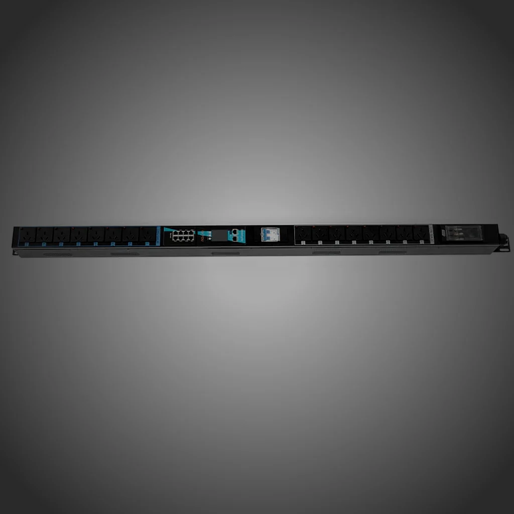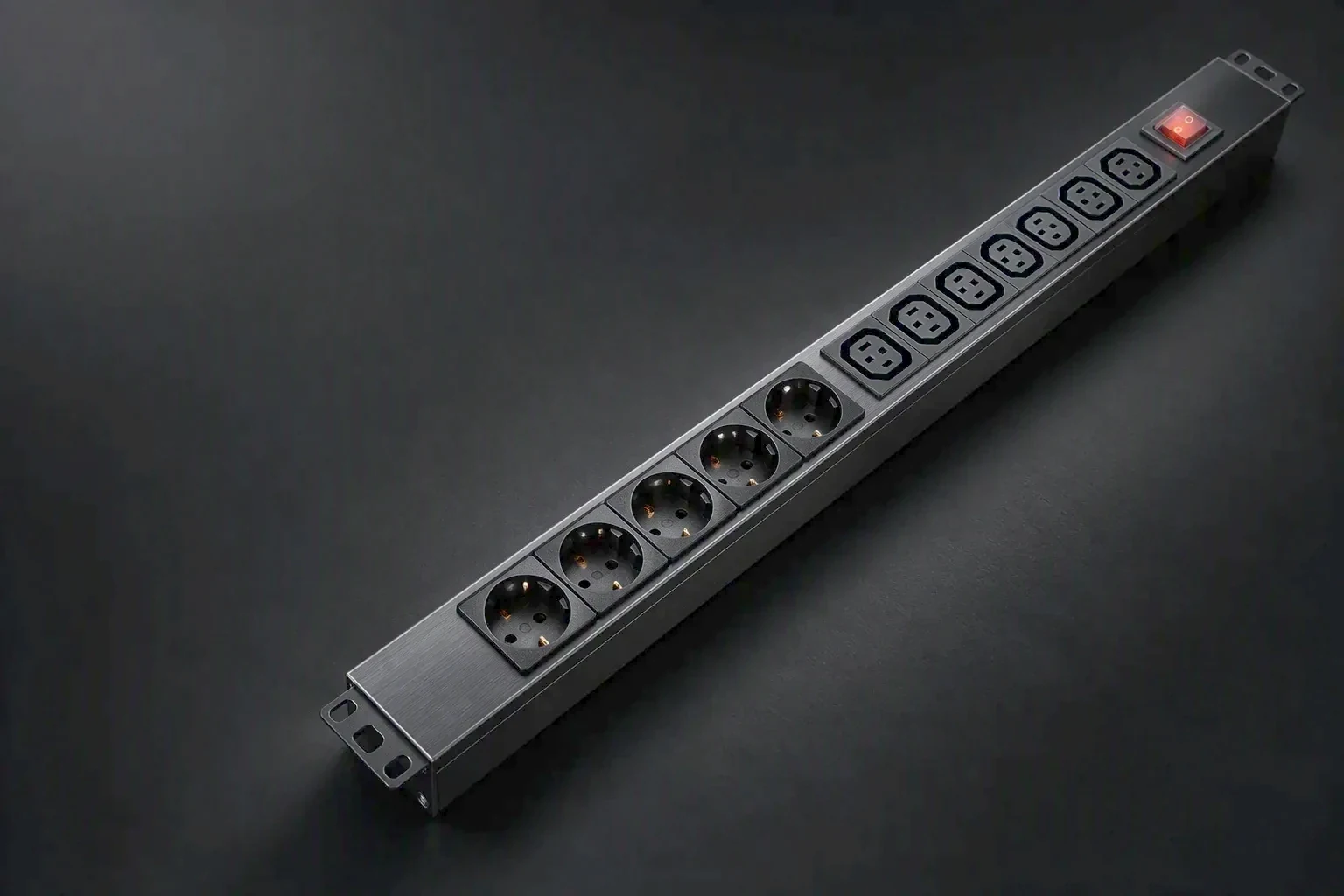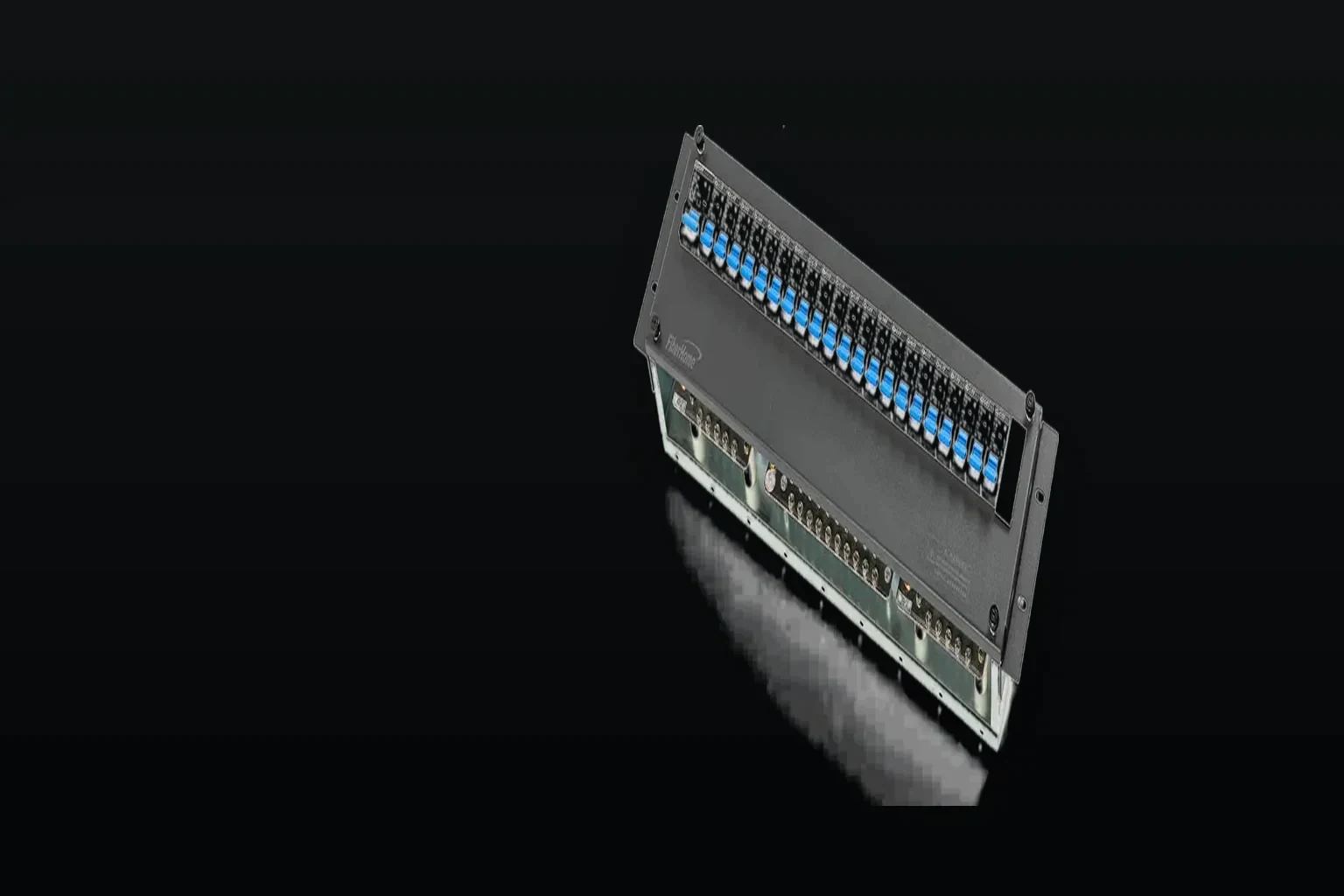
Mechanical & enclosure
Cold-rolled steel chassis, brushed face, mounted vertically at 0U or horizontally at 1U. Internally, VDE 2.5mm² and 6mm² conductors, joined on busbar.
- Enclosure
- Cold-rolled steel
- Mounting
- 0U / 1U
- Conductors
- 2.5 / 6mm²
- Connection
- Busbar
 Structure and mounting
What the chassis fixes
Enclosure material, mounting orientation, outlet order and conductor sizes are decided together, because each one constrains the others. Every value below is a published figure.
- Enclosure material
- Cold-rolled steel
- Face finish
- Brushed
- Vertical mounting
- 0U, inside the rack rail
- Horizontal mounting
- 1U
- Outlet example
- C13 × 36 + C19 × 4
- Outlet types
- IEC C13 10A · IEC C19 16A
- Internal conductors
- VDE 2.5mm² / 6mm²
- Joint type
- Busbar connection
- Cable entry
- Set by the drawing
- Local display
- Industrial OLED on the face
- Mounting hardware
- Supplied with the unit
- Rated example
- AC 415V, 20 × 20A
- Input current
- 10A–32A
- Rack hardware
- Server cabinet and open frame
- Custom variant
- Drawn to a customer drawing or sample
 Mounting decision
0U vertical or 1U horizontal
A vertical unit leaves rack units free and puts outlets beside the servers they feed. A horizontal unit occupies 1U and keeps the outlet row reachable from the front.
- Vertical0U
- Horizontal1U
- Outlet exampleC13 × 36 + C19 × 4
- DisplayIndustrial OLED
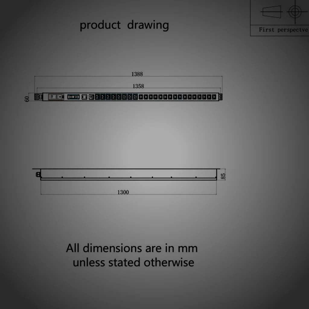
 Drawings before production
Built against a revision
- Outline drawingPer unit
- Outlet orderAs drawn
- First articleCompared to drawing
- RevisionConfirmed in writing
 From requirement to mechanism
Why the outlet order is drawn before the chassis is cut
Outlet order sets the sheet-metal break positions, the busbar run and the cable entry. Changing it after the chassis is cut means a new panel, and a new first-article comparison. Drawing it first is what keeps a mixed C13 and C19 build repeatable from one order to the next.
- Outlet types on the drawing
- IEC C13 10A · IEC C19 16A
- Example combination
- C13 × 36 + C19 × 4
- Vertical build
- 0U, rails not consumed
- Horizontal build
- 1U at the rack front
- Cable entry
- Fixed by the drawing revision
 Mechanical checkpoints
What is checked on the built unit
Six mechanical checkpoints, each one measurable against the drawing rather than judged by eye. A unit that fails any of them does not move to electrical test.
Enclosure material
Steel
Cold-rolled steel chassis with a brushed face, checked against the drawing before assembly closes.
Mounting orientation
0U / 1U
Vertical inside the rack rail, or horizontal at 1U; the fixing points follow the orientation.
Outlet order
36 + 4
C13 × 36 plus C19 × 4 on the reference build; order and count compared against the drawing.
 Conductor size
2.5–6mm²
VDE 2.5mm² and 6mm² conductors, sized to the current of the feed.
Joint method
Busbar
Busbar connections rather than daisy-chained terminals, so the current path is a solid run.
 First article
1 / series
The first unit of a series is compared against the drawing before the run continues.
 Mechanical release path
From orientation to dispatch
Three stages, in order. The mounting orientation is fixed at the first stage, because it decides where the outlets sit and where the cable enters.
Orientation and outlet list
Vertical 0U or horizontal 1U is chosen, and the outlet list is written with the count per type. Cable entry follows from both.
Outline drawing
Chassis, break positions, busbar run and fixing points are drawn by unit. The revision is confirmed in writing before any panel is cut.
First article and test
The first unit is compared against the drawing on dimensions, outlet order and conductor sizes, then goes through the electrical test on every line.
Mechanical request
Give us the rack, we draw the enclosure
State the mounting orientation and the outlet combination, and the outline drawing comes back by unit with the fixing points, the cable entry and the outlet order marked.
Reply within 12 hours on working days · no lead time or minimum quantity figure is published on this site.