Wiring & conductors
Internal VDE 2.5mm² and 6mm² conductors, terminated on busbar rather than chained through terminals. The wide-range input runs 180–265V with surge protection.
- Conductors
- VDE 2.5 / 6mm²
- Joints
- Busbar
- Wide input
- 180–265V
- Surge
- Fitted
 Conductor schedule
Conductors, joints and protection
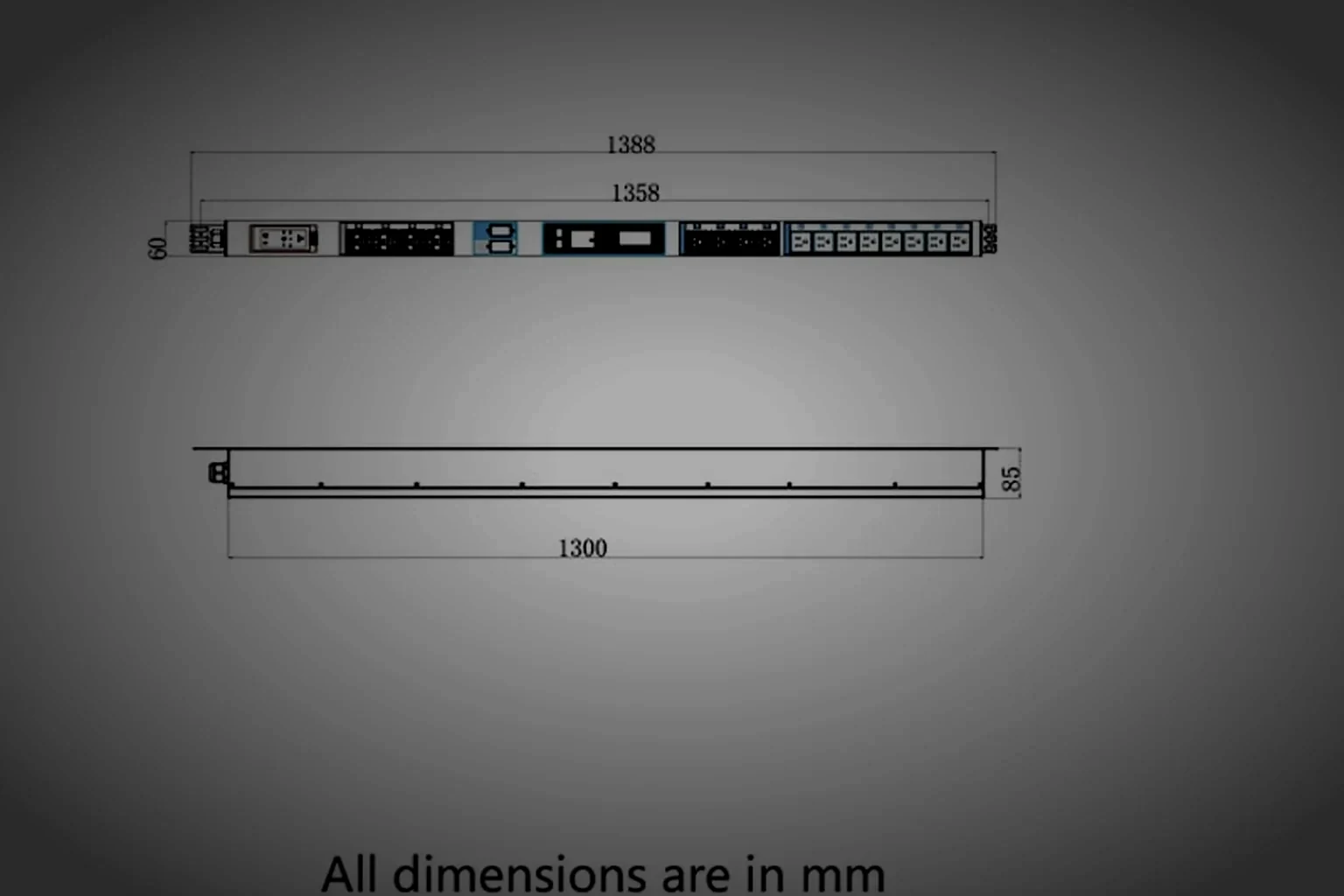
Conductor size is set by the current of the feed, and the joint method is set by the conductor size. Both appear on the drawing, so the schedule can be checked before the unit is wired.
- Internal conductor
- VDE 2.5mm²
- Internal conductor, heavy
- VDE 6mm²
- Joint type
- Busbar connection
- Wide-range input
- 180–265V
- Surge protection
- Fitted on the input
- Lightning protection
- Fitted on the input
- Input current
- 10A–32A
- Output current
- 10A–16A
- Operating voltage
- 110V~250V AC
- Operating frequency
- 50Hz~60Hz
- Outlet types
- IEC C13 10A · IEC C19 16A
- Outlet example
- C13 × 36 + C19 × 4
- Rated example
- AC 415V, 20 × 20A
- Temperature sensor
- -30°C~100°C, 1°C resolution
- Termination check
- Continuity and polarity, per line
Why busbar
A solid run, not a chain
A busbar carries the current of a feed as one continuous conductor. A chained terminal block adds a joint at every outlet, and every joint is a point that can loosen.
- Current pathOne run
- Joints per outletNone
- ConductorVDE 2.5 / 6mm²
 Protection on the feed
Surge, then overcurrent
- Wide-range input180–265V
- SurgeFitted
- OvercurrentBreaker or hydraulic
- Frequency50Hz–60Hz
 From requirement to mechanism
Conductor size is a thermal decision
A conductor undersized for its feed heats at the joint, and heat at a joint raises resistance, which raises the heat again. Sizing to the current of the feed breaks that loop: 2.5mm² on the light feeds, 6mm² on the heavy ones, both terminated on busbar so the current path stays solid from the input to the outlet row.
- Light feed conductor
- VDE 2.5mm²
- Heavy feed conductor
- VDE 6mm²
- Joint type
- Busbar, no chained terminals
- Test on the joint
- Continuity and polarity per line
 Wiring checkpoints
Six points checked on the loom
Each row below is a wiring fact that can be verified against the drawing and the test record, rather than a description of how the unit is assembled.
Light feed conductor
2.5mm²
VDE conductor used on the light feeds;.
Heavy feed conductor
6mm²
VDE conductor used on the heavy feeds, sized to the current of the feed.
Feed current band
32A
Input from 10A to 32A; output from 10A to 16A depending on the series.
Wide-range input
180–265V
With surge and lightning protection fitted on the input side of the feed.
 Overcurrent device
2types
Breaker or hydraulic-magnetic, selected with the series and the current of the feed.
 Termination test
100%
Continuity, polarity and insulation tested on every unit, recorded per line.
 Wiring release path
From conductor schedule to test record
Three stages, in order. Conductor size is fixed at the second stage, against the current per feed that the buyer supplies at the first.
Feed and protection
Current per feed, operating voltage and the protection required are written down. The wide-range input is chosen here if the site voltage moves.
Conductor schedule
Conductor size and joint method are set against the feed: VDE 2.5mm² or 6mm², on busbar, with the outlet order carried through from the drawing.
Termination test
Continuity and polarity are checked per line and insulation per unit. Any re-termination is recorded against the unit before it leaves the bench.
Wiring request
State the current per feed, we size the conductors
Current per feed and the outlet combination are what fix the conductor schedule. The reply carries the specification sheet per line and the outline drawing with the conductor sizes marked.
Reply within 12 hours on working days · no lead time or minimum quantity figure is published on this site.